Reform Text is a tool for Adobe Illustrator which allows the creation of beautiful text-on-a-path effects. Rather than simply rotating each character, Reform Text sculpts the text, so it flows naturally along the path, whilst positioning along the path is intuitive. Curve correction can be used to enhance results around sharp bends, while interactive variable height and acceleration controls allow users to refine text distortion.
Reform is a unique plugin for Adobe Illustrator which lets you intuitively sculpt and reprofile a portion of—or an entire—path. It avoids the need to individually adjust (or even think about) multiple anchor points and Bézier handles that normally defines the path. The region of the path to reshape can be set between two end markers or applied as a variable offset around the whole path. Astute Graphics' unique and powerful variable offset path technology is masked by Reform's ease of use, ensuring creatives can concentrate on making the shapes they want.
The Reprofile Tool allows you to apply repeating vector profiles to any path. Similar to how designers make use of Brushes, Reprofile creates clean results which can easily be edited further. Supplied with a set of default profiles, it's easy to get started and then create and save your own, managed in the Profile Manager available for use in all documents.
Set aside just 2-10 minutes and learn a new vector-based skill. Whether you’re an illustrator beginner or vector pro, you will find an invaluable nugget, or 50, to help you save time and be more creative in Illustrator!
You don't have to be an expert in Illustrator to use Reform. Learn how to sculpt any path without fiddling with bezier handles.
Learn how to use Reform and Reprofile in tandem to speed up your vector workflow.
Delve deeper into Reprofile and learn how to create your own profiles, and how to save them for future use.
Reform is a plugin for Adobe Illustrator which lets you “re-form”, or reshape, an entire path or a portion of a path without having to individually adjust or even worry about the individual anchor points and bezier handles that make up the path. It consists of a tool and an associated panel.
After installing the plugin, the Reform tool will show up in Illustrator's main toolbar (which must be in Advanced mode: Window > Toolbars > Advanced):
Click on the Reform tool in the toolbar to select it. If you use the tool frequently, you may want to assign it a keyboard shortcut key through Illustrator's Keyboard Shortcuts dialog (Edit > Keyboard Shortcuts...). You can also click on the Reform panel to select the Reform tool.
If you have Astute Graphics' DirectPrefs plugin installed, and its Auto Open Astute Graphics Panels preference enabled (enabled by default), then selecting the Reform tool will automatically show the Reform panel. Otherwise, if the panel is not visible, choose Window > Astute Graphics > Reform. While the Reform panel is not required in order to use the tool and reshape paths, it does contain various settings, options and commands that can only be accessed there.
For now, with a document open, simply hover the Reform tool's cursor over a basic open path. The path (or a section of it) will highlight (the default color is blue). Press the mouse button down and drag with the tool. You will see a new, red line appear, which is a preview of the reshaped path. How far you drag determines how far the reshaped path bends away from the original.
To finalize the reshape, press the Return or Enter key, or click the Apply button on the Reform panel. The newly-reshaped path remains selected. Alternatively, Option/Alt + Return or Enter, or holding down Option/Alt when clicking the Apply button will create a duplicate of the reshape path, maintaining the original as-is.
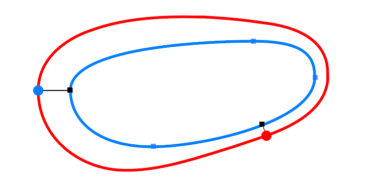
This diagram shows a path in the process of being reshaped, or “sculpted”, using the Reform tool (with the default interface settings).
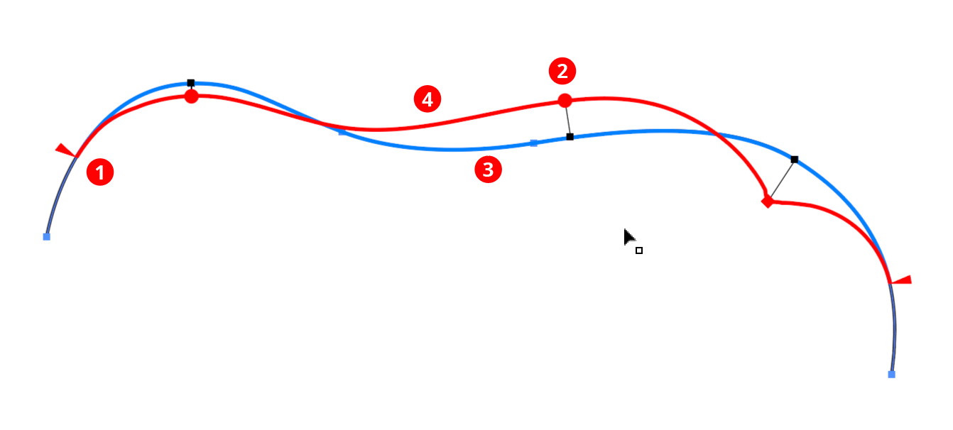
The following items are shown:
1. Start and End Delimiters (red triangles): The delimiters mark the section of the path that will be affected by the reshape. Initially, they are put at the nearest corner points on either side of the clicked or dragged segment. If the entire path is smooth, the delimiters will be placed at the ends of the path (for an open path) or at point zero (for a closed path).
2. Offset Markers (red circles/diamonds): Markers represent points along the path where you specify how far to offset the path from its original position. A marker's position along the path is indicated by a small black square, joined to it by a thin black line whose length represents the offset distance. Except in certain situations, the reshaped path will thus pass through each marker.
Markers drawn as circles are “smooth” markers: the reshaped path passes smoothly through them.
Markers drawn as diamonds are “sharp” markers: the reshaped path can make an abrupt angle change there.
You can use any number of markers to reshape a path, but, like anchor points, for the smoothest results you should use the fewest number that still produce the shape you want.
3. Original Path (blue path): The original shape of the path (or section of the path) is drawn as a blue line.
4. Virtual Reshaped Path (red path): The reshaped path is “virtual” because the underlying path art is not actually changed until you finalize the reshaping. Until this is done you may continue to refine it (e.g. by moving the delimiters, editing the markers, or changing parameters on the panel) or, if you change your mind, by resetting the Reform tool, thereby removing all annotations.
The delimiters can be moved by dragging them. To disable snapping to anchor points, hold down Command (Mac) or Ctrl (Windows) while dragging. To quickly move the delimiters so that the entire path is affected by the Reform tool, double-click either one of them. For an open path, this will move them to the path's endpoints. For a closed path, this will enter “looped mode” (see below). If a delimiter is dragged such that a marker would fall outside of the newly-delimited portion of the path, the marker will be automatically deleted. If a marker is located exactly on a delimiter, then moving the delimiter will also move the marker.
Markers can be moved by dragging them within the delimited reshape extent. To disable snapping to the path's underlying anchor points, hold down Command (Mac) or Ctrl (Windows) while dragging. Dragging a marker by its circle annotation will allow you to freely change both its position along the path and its offset; to change only its offset, hold down Shift while dragging.
To change only its position, drag the marker's black line or black square annotation.
Multiple markers can be moved simultaneously if they are selected.
To select a single marker, click on its circle annotation.
Multiple markers may be selected by Shift-clicking them or by dragging a marquee over them in the normal manner.
To delete a marker, double-click its circle.
To create an additional marker, place the cursor over either the original or virtual reshaped path and click or click-and-drag.
To change a marker from smooth to sharp or vice versa while dragging it, press the “X” key.
When using the Reform tool, Astute Graphics’ AstuteBuddy panel should be kept open to show relevant keypresses.
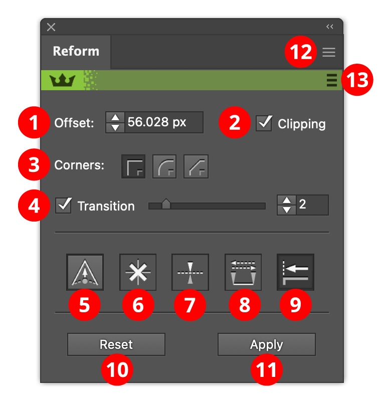
1. Offset value: Lets you numerically enter the offset value of the selected markers. Note that negative values are allowed, and push the path in the opposite direction from a positive value.
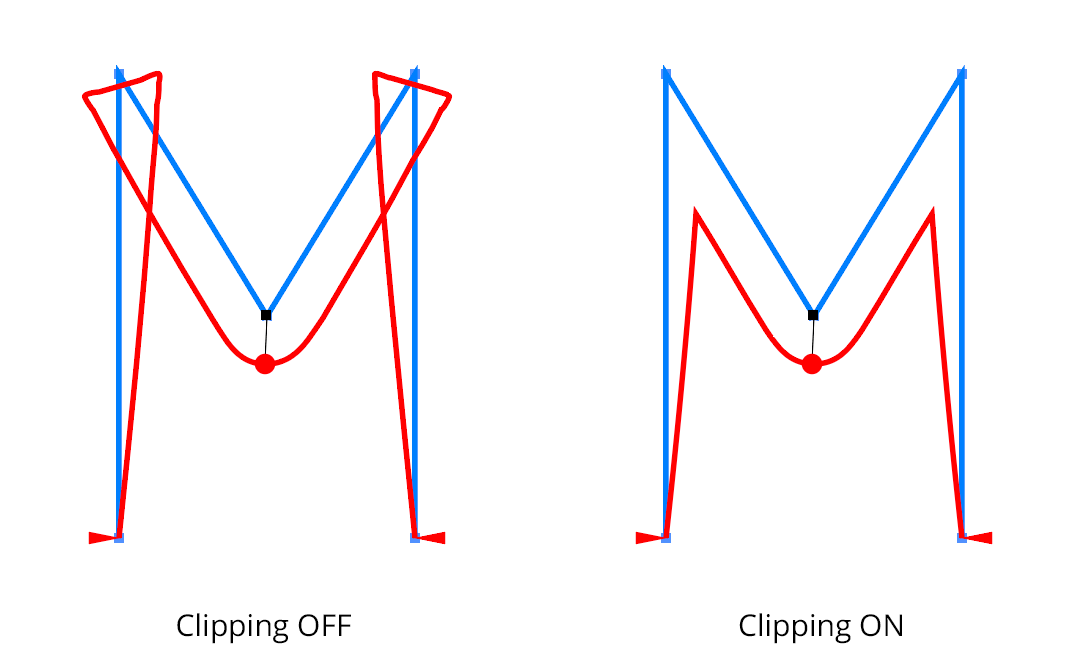
2. Clipping checkbox: Turns on and off clipping. Clipping is useful when the specified offsets cause the path to cross over itself, by removing those loops:
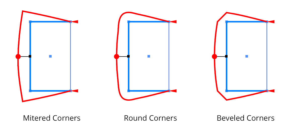
3. Corners buttons: When reshaping a path with an abrupt change in path direction, the corner type specifies how the reshaped path bends around the original corner:
4. Transition checkbox/value: Controls the smoothness of the transition between the original path and its reshaped portion (Off, or values of 1-10):
5. Sharp marker button: Toggles the selected markers between smooth and sharp (see above for explanation of different types). It also controls the type of any newly-created markers.
6. Delete marker button: Removes all selected markers.
7. Mirror offset button: Changes the direction of the offset of all selected markers. This is the same as changing the sign of the offset value.
8. Swap marker direction button: Changes the position of all markers (selected or not) along the reshape extent. If, for example, a marker is located 1/5 of the way from the start to the end delimiter, swapping the direction will change it to be 1/5 of the way from the end to the start delimiter. Offset values are not changed.
9. Smart Joining button: See “Smart Joining”, below.
10. Reset button: Cancels the reshape operation. The path remains unmodified. This can also be achieved by pressing the Esc key when the cursor is in motion.
11. Apply button: Finalizes the path reshape. This can also be achieved by pressing Return or Enter.
12. Flyout menu: Provides access to the preferences dialog, and allows saving and recalling of profiles (see below).
13. Banner menu: Provides links to the Astute Graphics website.
When reshaping an entire closed path, delimiters are not necessarily helpful, because, in a sense, the path does not have a beginning and an end. In this case you may use “looped mode”. In this mode, which is only applicable for closed paths, there are no delimiters. Instead, there is a special blue marker pair which is located at “point zero” along the path and cannot be moved or deleted. If point zero is smooth, the pair will appear as a single marker; if point zero is a corner point, the markers will appear separately. In either case, the pair's common length may be adjusted by dragging either of the blue markers to set the offset of the path at that point. Additional normal markers may be set at other positions along the path.
To enter looped mode on a closed path which is already being reshaped, double-click either one of the delimiters. To enter looped mode immediately when starting a new reshape, hold down Option (Mac) or Alt (Windows) when initially clicking or dragging the path.
Since the entire path is affected in looped mode, the Transition parameter is no longer applicable.
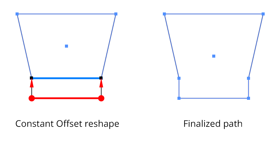
A common operation is to extend one section of a path by a uniform amount. You can achieve this by placing markers of equal offset value exactly on the start and end delimiters. To save time, you may quickly create a constant offset by holding down Shift-Option (Mac) or Shift-Alt (Windows) while initially dragging the path to create a new reshape:
In the above example of a Constant Offset reshape, it is natural to want the offset path section to extend from the original path at its original angle. This is where “Smart Joining” provides a solution. With Smart Joining enabled (by clicking the button on the panel), Reform will, when possible, try and extend the path section while keeping the path's original angle:
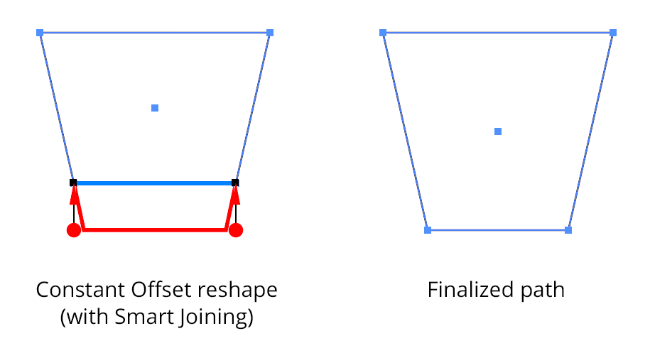
When dragging out a constant offset, you can toggle Smart Joining by pressing the S key. The Smart Joined extension is always straight, even if the path is curved.
Reform has an internal Undo/Redo system that keeps track of all changes as you refine the profile. If you move a marker, for example, but then want to put it back exactly where it was, you can simply undo your last change. Reform uses the keystrokes that Illustrator assigns to the tool commands “Decrease/Increase Diameter” to do this. By default, these are the left and right square bracket keys respectively ( [ and ] ), but these may be reassigned, as with any keyboard shortcut.
Resetting or applying a Reform profile clears the Undo/Redo history. To save a profile, see below.
The Reform Preferences dialog may be opened by either double-clicking the Reform tool icon in the toolbar, or by choosing “Reform Preferences...” at the top of the panel flyout menu (#12 on the annotated panel screenshot above).
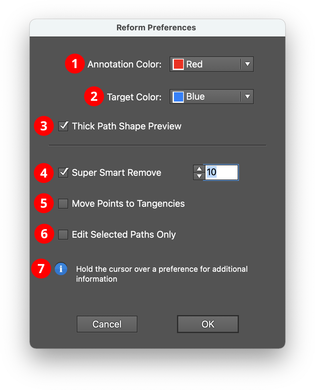
1. Annotation Color: The main color used to draw the reshaped path, markers, and delimiters; red by default.
2. Target Color: The color used to show the original path. It is also used for loop mode markers; blue by default.
3. Thick Path Shape Preview checkbox: When enabled, the original and reshaped path previews are drawn with a thick line, and larger marker annotations are used.
4. Super Smart Remove checkbox/value: When enabled, unnecessary anchor points are removed from the final reshaped path, using the value as a tolerance. Higher tolerance values will remove more points but may make the final path vary from its preview slightly.
5. Move Points to Tangencies checkbox: When enabled, points along the reshaped path will be located at horizontal and vertical tangencies when possible.
6. Edit Selected Paths Only checkbox: When enabled, paths must be selected before the Reform tool will edit them.
7. Informational area: Shows a brief description of each preference setting when the cursor is being held over it.
"Profiles” (sequences of offset markers along a delimited extent) may be saved and recalled, so that multiple paths may be reshaped in the same manner. To save a profile, use the panel flyout menu when a reform operation is in progress and choose Save Profile... and give the profile a name. To apply an existing profile to a path, start editing the path with the Reform tool and (if necessary) move the delimiters to the desired positions. Then choose the desired profile from the panel flyout menu.
Note that parameters such as transition and clipping are not saved with the profile.
Profiles may be renamed or deleted by choosing Manage Profiles... from the panel flyout menu.
Reform gives the best results when it is used to make subtle changes to paths. Very large offsets will often produce unpredictable results, especially at corners.
We are always striving to improve our plugins. We encourage you to report bugs or inconsistencies, as well as ideas for new features or other ways to make the plugin perform better for you.
Reprofile is a plugin tool for Adobe Illustrator which lets you add a "profile", or extra geometry, to an entire path or portion of a path. It is designed to add complexity to basic paths, whilst keeping the broad path shape the same. It consists of a tool and an associated panel, together with dialogs for managing the library of supplied and user-defined profiles.
After installing the plugin, the Reprofile tool will show up in Illustrator's main toolbar (which must be in advanced mode: Window > Toolbars > Advanced).
Click on the Reprofile tool in the toolbar to select it. If you use the tool frequently, you may wish to assign it a keyboard shortcut key through Illustrator's Keyboard Shortcuts dialog (Edit > Keyboard Shortcuts...). You can also click on the Reprofile panel to activate the Reprofile tool.
If you have Astute Graphics' DirectPrefs plugin installed, and its Auto Open Astute Graphics Panels preference enabled (enabled by default), then selecting the Reprofile tool will automatically show the Reprofile panel. Otherwise, if the panel is not visible, choose Window > Astute Graphics > Reprofile.
While the Reprofile panel is not required in order to use the tool and reshape paths, it does contain various settings, options and commands that can only be accessed there, in particular, you will need the panel to select the Profile to apply.
For now, with a document open, simply hover the Reprofile tool's cursor over a basic path. The path (or a section of it) will highlight (the default color is blue). Press the mouse button down and drag out with the tool. You will see a new, red line appear, which is a preview of the reprofiled path. How far you drag determines the height of the profile applied to the path at that point. The blue outlines are for visual guidance only, they will not appear when the profile is applied.
To finalize the reprofile, press the Return or Enter key, or click the Apply button on the Reprofile panel. The newly-reprofiled path remains selected. If the profile contains more than one path, the target path will be turned into a compound path. If the key path of the profile is suppressed, a closed target path will become an open target path.
To add the reprofiled path, whilst still keeping the original, Option (Windows) / Alt (mac) + Return or Enter, or holding down Option/Alt when clicking the Apply button, will retain the original artwork, creating the reprofiled section above it.
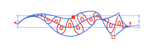
This diagram shows a path in the process of being reshaped, or “reprofiled”, using the Reprofile tool (with the default interface settings).
The following items are shown:
1. Start and end delimiters (red triangles): The delimiters mark the section of the path that will be affected by the reshape. Initially, they are put at the nearest corner points on either side of the clicked or dragged segment. If the entire path is smooth, the delimiters will be placed at the ends of the path (for an open path) or at point zero (for a closed path).
2. Offset markers (red squares): Markers represent points along the path where you specify the height of the profile. A marker's position along the path is indicated by a small black square, joined to it by a thin black line whose length represents the offset distance.
The selected marker (filled square) is “smooth”. The profile height changes smoothly through it.
The unselected marker (open square) is “sharp”. The profile height changes abruptly at this marker.
You can use any number of markers to reshape a path, but, like anchor points, for the smoothest results you should use the fewest number that still produce the shape you want.
3. Mirrored offset lines (dashed lines): If the profile extends in both directions, a mirrored line appears. This is purely a visual guide and cannot be interacted with.
4. Target path (blue path): The original shape of the path (or section of the path) is drawn as a blue line.
5. Guide path (blue paths): The blue lines give a guide to the height of the profile. Clicking on the top guide path will add a marker. The guide path is only approximate, especially for mitered corners, due to the way Reprofile warps geometry at corners. The guide paths will cross if markers are dragged to opposite sides of the target path.
6. Virtual reshaped path (red path): The reshaped path is “virtual” because the underlying path art is not actually changed until you finalize the reshaping. Until this is done you may continue to refine it (e.g. by moving the delimiters, editing the markers, or changing parameters on the panel) or, if you change your mind, by resetting the Reprofile tool, thereby removing all annotations.
7. Profile: The profile being used here is the “Wiggle Round 2” from the supplied sample profile. It is repeated several times along the target path
8. Key path: The wavy line is the “key path”. It replaces the target path. The circles are not key paths, if present non-key paths are added to the new path as elements of a compound path.
The delimiters can be moved by dragging them. To disable snapping to anchor points, hold down Command (mac) or Ctrl (Windows) while dragging. To quickly move the delimiters so that the entire path is affected by the Reprofile tool, double-click either one of them. For an open path, this will move them to the path's endpoints. For a closed path, this will enter “looped mode” (see below). If a delimiter is dragged such that a marker would fall outside of the newly-delimited portion of the path, the marker will be automatically deleted. If a marker is located exactly on a delimiter, then moving the delimiter will also move the marker.
Markers can be moved by dragging them within the delimited reshape extent. To disable snapping to the path's underlying anchor points, hold down Command (mac) or Ctrl (Windows) while dragging. Dragging a marker by its circle annotation will allow you to freely change both its position along the path and its offset; to change only its offset, hold down Shift while dragging.
To change only its position, drag the marker's black line or black square annotation.
To select a single marker, click on its circle annotation.
Multiple markers may be selected by Shift + clicking them or by dragging a marquee over them in the normal manner. They can then be moved simultaneously.
To delete a marker, double-click its red square.
To create an additional marker, place the cursor over either the original or virtual reshaped path and click or click-and-drag.
To change a marker from smooth to sharp or vice versa while dragging it, press the “X” key.
When using the Reprofile tool, Astute Graphics’ AstuteBuddy panel should be kept open to show relevant keypresses.
When reprofiling an entire closed path, the target path does not have a beginning and an end. In this case you may use “looped mode”. In this mode, which is only applicable for closed paths, there are no delimiters. Instead, there is a special blue marker pair which is located at “point zero” along the path and cannot be moved or deleted. If point zero is smooth, the pair will appear as a single marker; if point zero is a corner point, the markers will appear separately. In either case, the pair's common length may be adjusted by dragging either of the blue markers to set the height of the path at that point. Additional normal markers may be set at other positions along the path.
To enter looped mode on a closed path which is already being reshaped, double-click either one of the delimiters. To enter looped mode immediately when starting a new reshape, hold down Option (Windows) or Alt (mac) when initially clicking or dragging the path.
Since the entire path is affected in looped mode, the Transition parameter is no longer applicable.
A common operation is to extend one section of a path by a uniform amount. You can achieve this by placing markers of equal height value exactly on the start and end delimiters. To save time, you may quickly create a constant offset by holding down Shift + Option (Windows) or Shift + Alt (mac) while initially dragging the path to create a new reprofile.
Reprofile has an internal Undo/Redo system that keeps track of all changes as you refine the profile. If you move a marker, for example, but then want to put it back exactly where it was, you can simply undo your last change. Reprofile uses the keystrokes that Illustrator assigns to the tool commands “Decrease/Increase Diameter” to do this. By default, these are the left and right square bracket keys respectively ( [ and ] ), but these may be reassigned, as with any keyboard shortcut.
Resetting or applying a Reprofile profile clears the Undo/Redo history, as does editing the profile library with the Profile Manager.
Reprofile comes with a set of standard sample profiles. It is possible to add user-defined profiles to the library, or to import and export profile files as xml data.
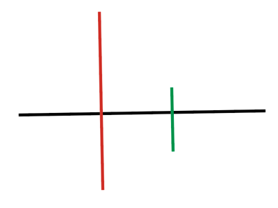
The key path defines the path which replaces the target path. Profile geometry cannot overhang the key path. In this profile, the black path or the red path can be used as the key path, but the green path cannot because of its short length.
To create a profile, draw the profile in Illustrator. Any styling or coloring will be stripped. The profiles have rubber sheet geometry, so height and width will be set by the tool. However dimensions should be within an order of magnitude of the expected final result to avoid scaling artifacts. The profile must contain at least one open path, which is used as the key path. It is not possible to create a profile without a legal key path. However the key path can be suppressed, meaning that it will not appear in the final result.
The key path cannot be overhung by any other artwork. Select the artwork to be used for the profile, open the Reprofile tool, and click the “Grab” button (the addition sign icon) in the main tool panel (see below). The Profile Attributes editor will open (see below). If the wrong path has been chosen as the key path, correct it in the Profile Attributes editor. If the default dimensions are not desired, enter the correct values. Accept the new profile by clicking the “OK” button, and the new profile will be added to the library. A unique name is assigned automatically, though usually you will wish to provide your own name.
To back up the profile, or to share it with other artists, open the Profile Manager (see below) to export it as an xml file. Profile Manager also allows the import of profiles, the deletion of unwanted profiles, and other library operations. Profile geometry cannot be edited once the profile has been created. To edit profile geometry, dump it to the artboard using the profile dump button (lightening icon, see below), edit it using Illustrator’s normal artwork tools, delete the old profile, and add it again to the library. As a shortcut it is possible to Option/Alt-click on the “Grab” button. This overwrites the geometry of the selected profile, whilst keeping the other attributes.
Sometimes it is desirable to create paths which join on profile boundaries to prevent the unit cell from being visually obvious. These may be detected as overhanging artwork, in which case paths will have to be adjusted by a tiny amount in Illustrator. The tool will join adjacent open paths, within a tolerance.
If the profile contains more than one path, the key path does not have to appear in the final result. There is an option to suppress it. It then acts purely as a guide to placement of the profile along the target path.
Text can be used as a profile. Select the text as usual and press the “Grab” button. It is not necessary to outline it, though Reprofile will outline the text internally and it will no longer be editable within the tool. A key path is automatically added at the baseline of the text, and suppressed by default. Alternatively, it is possible to supply a key path by adding an open path and selecting it along with the text when the profile is created.
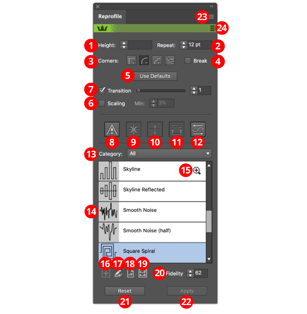
1. Height value: To numerically enter the height of the selected markers. Note that negative values are allowed and create a mirrored reprofile. It is possible to mix positive and negative markers.
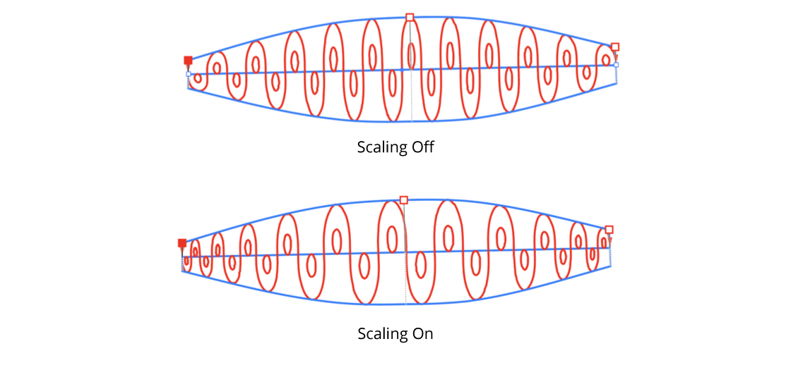
2. Repeat value: Sets the width of the profile element, in document units. Note that this will be rounded to create a whole number of repeats. If scaling is enabled, the value is the average width of the scaled elements.
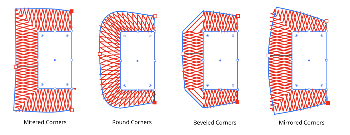
3. Corners buttons: When reprofiling a path with an abrupt change in path direction, the corner type specifies how the reprofiled path bends around the original corner.
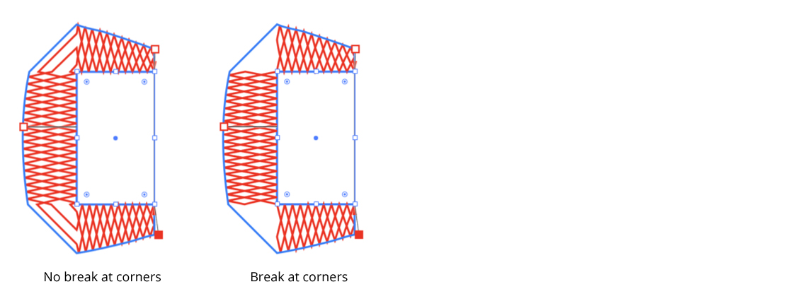
4. Break checkbox: Forces a whole number of repeats for each smooth section of the path without corners. This option is always enabled for mirrored corners.
5. Use Defaults button: Sets the parameters to the values stored for the profile in the Profile Library. These can be edited in the Profile Attributes panel.
6. Scaling checkbox and value: When selected, profile width is varied by the height of the profile at that point. The minimum scaling value sets a minimum scaling to prevent profiles at very low points being scaled to tiny sizes.
7. Transition checkbox / value: Controls the smoothness of the transition between the original path and its reprofiled portion (off, or values of 1 - 10).
8. Sharp marker button: Toggles the selected markers between smooth and sharp (see above for explanation of different types). It also controls the type of any newly-created markers.
9. Delete marker button: Removes all selected markers.
10. Mirror offset button: Changes the direction of the height of all selected markers. This is the same as changing the sign of the height value.
11. Swap marker direction button: Changes the position of all markers (selected or not) along the reshape extent. If, for example, a marker is located 1/5 of the way from the start to the end delimiter, swapping the direction will change it to be 1/5 of the way from the end to the start delimiter. Offset values are not changed.
12. Flip profile direction button: Toggles the profile direction horizontally along the path.
13. Category dropdown: Sets the category of profile to display in the selection panel.
14. Profile selection panel: Selects the profile to use for reprofiling.
15. Profile zoom icon: Toggles the profile thumbnail displayed in the profile selection panel between small and expanded. Shift + clicking will toggle all the profiles. This is purely to aid in profile selection, it does not affect the behaviour of the tool.
16. Grab button: If artwork is selected, it will take the artwork and open the Profile Attributes Editor (see below). If the profile is accepted, it will be added to the library. Option/Alt-click to overwrite the geometry of the currently selected profile (ie. edit the existing profile shape).
17. Profile edit button: Opens the Profile Attributes Editor to edit the attributes of the selected profile.
18. Profile dump button: Copies the selected profile to the artboard. Note that dumping and re-grabbing is the only way to edit the geometry of a profile.
19. Profile Manager button: Opens Profile Manager (see below). Profile Manager allows you to import, export, and delete profiles.
20. Fidelity control: Controls the accuracy with which paths are reprofiled. A high value means greater accuracy, but longer processing time. For technical reasons, artifacts will also occasionally appear if fidelity is too high. A lower fidelity value also maintains more straight lines. You might consider editing with a lower fidelity to retain interactivity, then setting the value higher before applying.
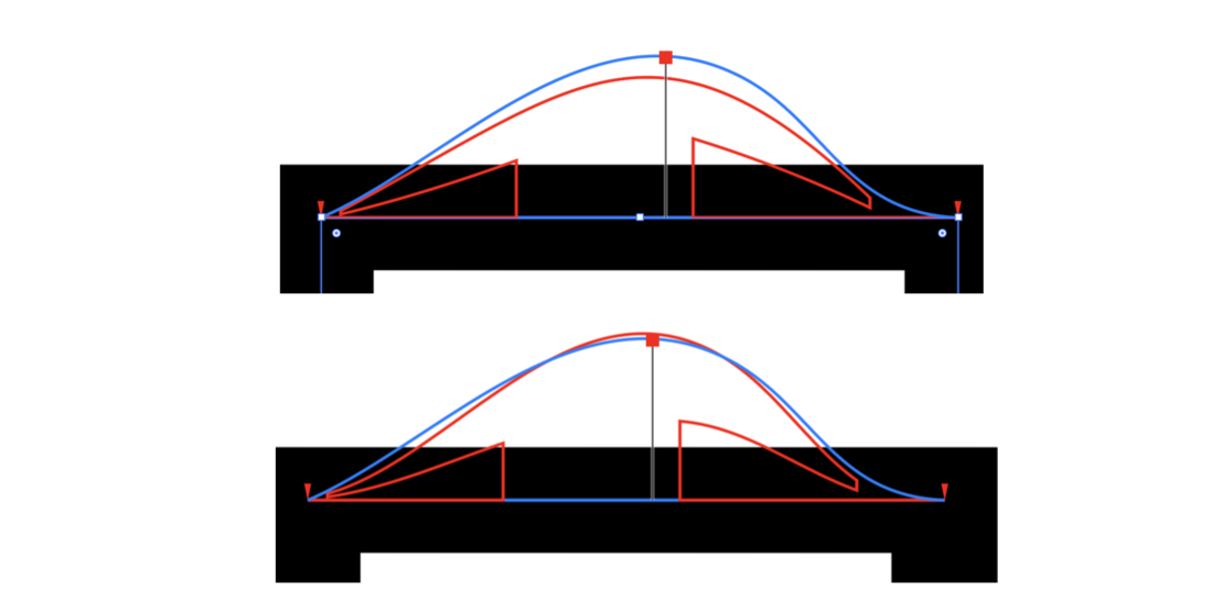
Scale: the thick black line is a path of one point width.
Low fidelity: the short lines are interpreted as straight lines.
High fidelity: the short lines are curved to follow the width profile.
21. Reset button: Cancels the Reprofile operation. The path remains unmodified. This can also be achieved by pressing the Esc key when the cursor is in motion.
22. Apply button: Finalizes the path reprofile. This can also be achieved by pressing Return or Enter. Holding down Alt / Option will cause the original artwork to be retained.
23. Flyout menu: Provides access to the preferences dialog, and allows saving and recalling of height marker settings (see below).
24. Banner menu: Provides links to the Astute Graphics website.
The Profile Attributes Editor allows editing of the metadata associated with the profile. It will not allow editing of the geometry itself (dump the profile to the artboard, edit it in Illustrator, and re-grab it to alter profile geometry). Not all artwork is suitable for use as a profile. If artwork is unsuitable, the editor will come up, but it will be impossible to accept the profile and the “OK” button will be greyed out. A diagnostic message will be shown explaining why the artwork cannot be accepted.
The Profile Attributes Editor comes up when a new profile is created by pressing the “Grab” button in the main tool panel (see above). Aside from giving the profile a name and setting the category, another important operation is setting the key path. The key path is used to replace the original path in the target art. The key path must be an open path, and it cannot be overhung by any other artwork. However it is possible to create artwork with more than one valid key path. A profile must be given a valid key path to be created.
The Profile Attributes Editor can be invoked from the Grab button or the Profile Edit button in the main tool panel.
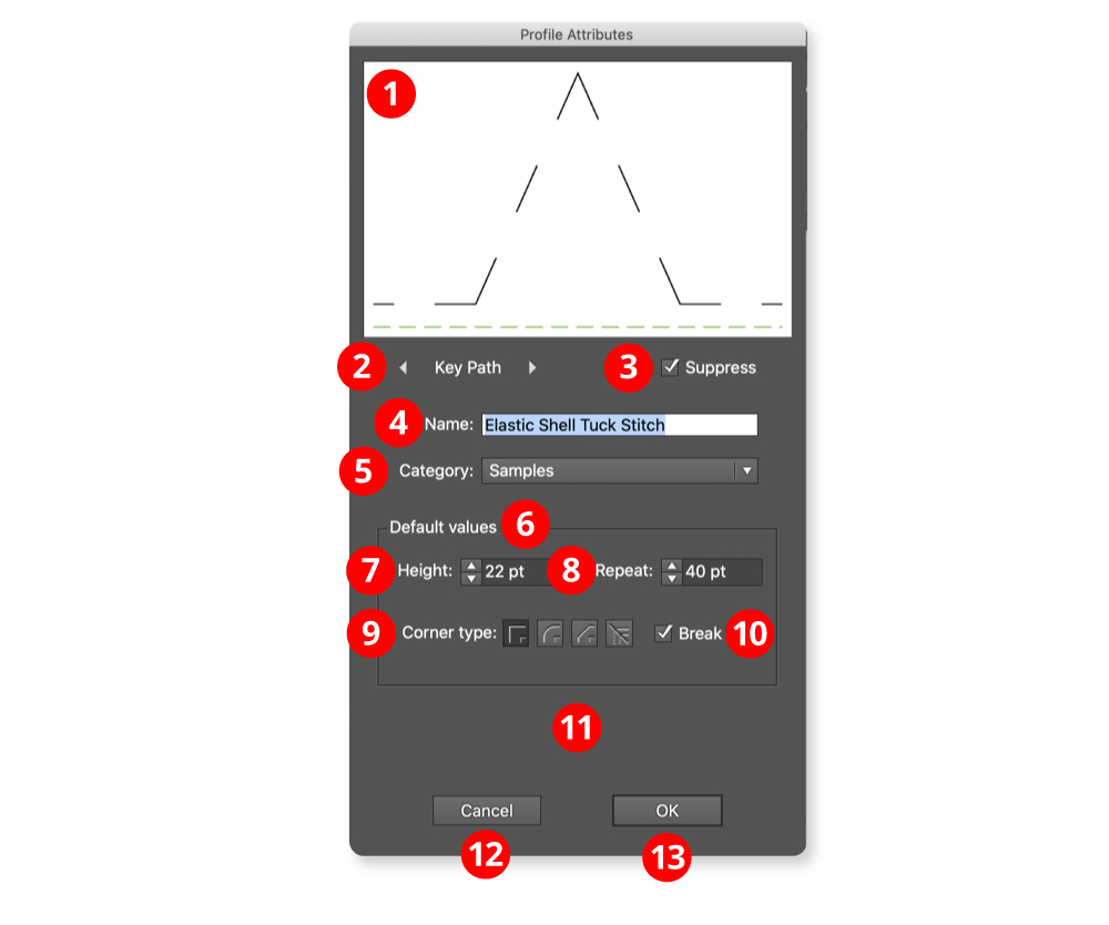
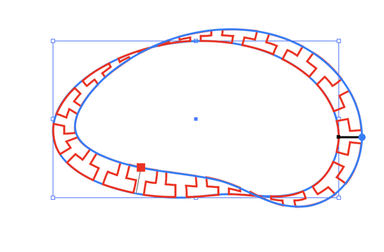
1. The Profile thumbnail: Profiles use rubber sheet geometry, so the aspect ratio of the artwork selected in Illustrator will not be preserved. The key path is shown in red, or in a dotted green line if it is suppressed. It is possible to interact with the thumbnail using the mouse to select the key path. The thumbnail will then rotate to show the new key path in the horizontal position.
2. Key path cycle buttons: If the artwork has only a few open paths, it may be more convenient to select the key path using the buttons. If the artwork has only one open path, they will be disabled. It is possible to select an invalid path as the key path, but not to accept the resulting profile (OK button is greyed out).
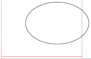
An invalid key path has been selected. The dotted lines show where artwork is overhanging. Note: Sometimes the overhang can be very small.
3. Suppress key path checkbox: If the key path is suppressed, it is shown as a dotted green line. The key path is used to align the profile to the target art, but doesn’t appear when the reprofile is applied. If only part of the target path is selected, a closed path will become an open path and an open path will be broken into two.
4. Name edit box: The name of the profile. Names are also used as filenames, so currently only Latin names that do not contain special characters are supported.
5. Category dropdown: Set the category of the profile. It is also possible to create a new category. Manage categories using the Profile Manger (see below).
6. Default values: These are the settings for the profiles which are set when pressing the “Use Defaults” button in the main tool panel (see above).
7. Height control: Default height of the profile, usually overridden by editing with the tool, but useful for preserving aspect ratio.
8. Repeat control: Default repeat width of the profile. Use with the height setting to preserve aspect ratio. Unlike height, repeat is not affected by editing with the tool.
9. Corner type buttons: When reprofiling a path with an abrupt change in path direction, the corner type specifies how the reprofiled path bends around the original corner. (See above).
10. Break checkbox: Forces a whole number of repeats for each section of the path without corners. This option is always enabled for mirrored corners (see above).
11. Information area: If the profile cannot be accepted, explanatory text appears here and the “OK” button is greyed out.
12. Cancel button: Cancels the profile edit, or cancels the profile creation if dialog invoked from the “Grab” button.
13. OK button: Accepts the edits or the new profile and saves it in the library. Note: that if creating a new profile it may not be possible to accept it and the OK button will always be greyed out. This is so it is possible to examine the profile to find the problem, which will usually be artwork overhanging the key path.
The Profile Manager is used for editing the Profile Library. There is some overlap with the Profile Attributes editor, which is intended for editing metadata associated with a single profile. Profile Manager operates on the library as a whole.
The "Sample profiles," which are automatically added when Reform is first installed, can be edited or deleted like profiles you create yourself. When all profiles are deleted, the Sample profiles will be reset. Profiles can also be exported or imported in an open xml format. This allows the sharing of profiles and the creation of backup files.
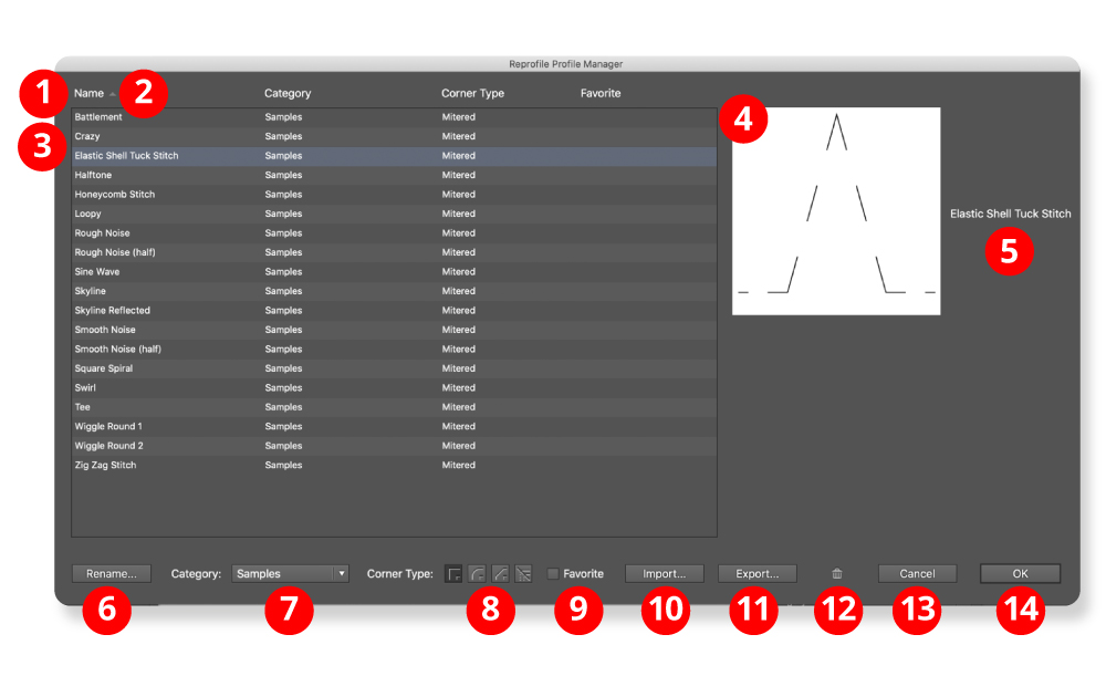
1. The field headers: The field headers sort on the field when clicked. If the field is already selected, the sort order is toggled.
2. Sort order arrow: Shows whether the sort is ascending or descending.
3. The Profile list: Every profile in the library is listed. It is possible to select a single profile or a group of profiles. Profile Manager edit operations always operate on the selection.
Fields are:
Name: the name of the profile
Category: the category to which the profile is assigned, or “None”.
Corner type: behaviour at sharp joins in the target path.
Favorite: set if the profile is a favorite
4. Profile thumbnails: Shows up to sixteen profiles for preview. Profiles have rubber sheet geometry so aspect ratio with drawn artwork will not be preserved. If width is much greater than height, it decides intelligently whether to display the profile as repeating elements or to stretch it.
5. Names: Profile names displayed here to identify the thumbnails.
6. Rename button: Brings up a dialog to rename the selected profile. (The Profile Attributes Editor may also be used to set the name).
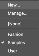
7. Category dropdown: Sets the category of the selected profiles. The “New…” option brings up a dialog to create a new category (the Profile Attributes Editor may also be used). The “Manage…” option brings up the Category Manager dialog, which allows the renaming, deletion, or creation of categories (not available from the Profile Attributes Editor).
8. Corners buttons: When reprofiling a path with an abrupt change in path direction, the corner type specifies how the reprofiled path bends around the original corner.
9. Favorite checkbox: To mark a profile as a favorite for easy selection.
10. Import button: Brings up a dialog to import profiles from xml files. The library stores the profiles as a flat list, so names cannot be duplicated. It will attempt to intelligently resolve name conflicts.
11. Export button: Brings up a dialog to export the selected profiles. Profiles are exported as open xml files. The profile name is stored in the xml data so the name of the file can be changed without affecting the library name.
12. Delete button: Deletes the selected profiles. Delete every profile to reset the library to the original sample profiles on next start-up.
13. Cancel button: Cancels every library editing operation, including import operations, but not export operations.
14. OK button: Accept the edits and updates the profile library. This will purge the undo list if the Reprofile tool is active.
The Reform Preferences dialog may be opened by either double-clicking the Reform tool icon in the toolbar, or by choosing “Reform Preferences...” at the top of the panel flyout menu (#23 on the annotated panel screenshot above).
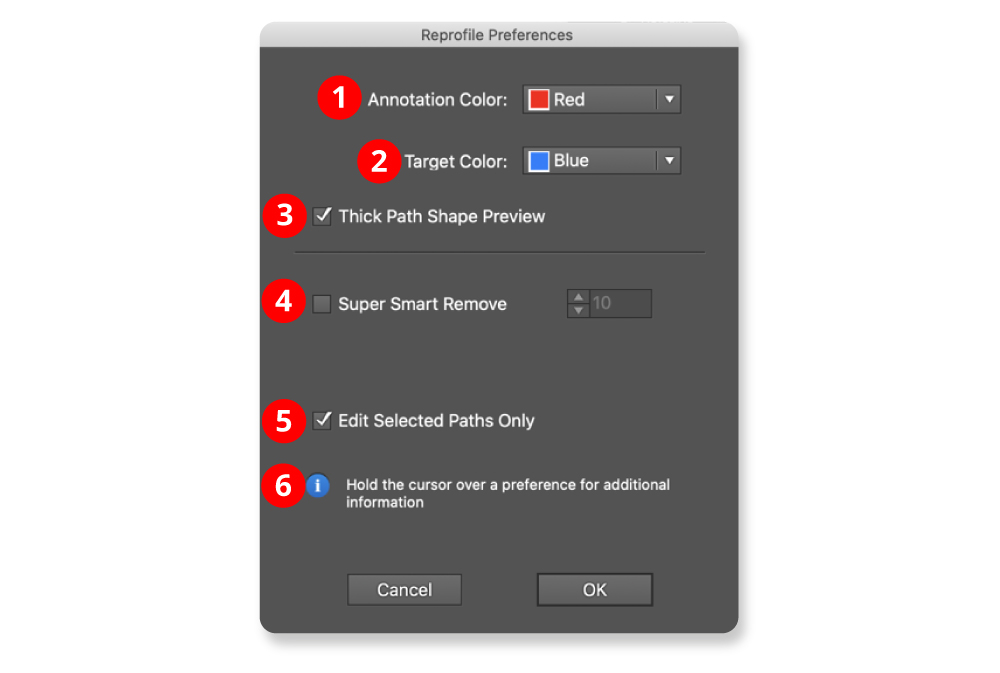
1. Annotation Color: The main color used to draw the reshaped path, markers, and delimiters; red by default.
2. Target Color: The color used to show the original path. It is also used for loop mode markers; blue by default.
3. Thick Path Shape Preview checkbox: When enabled, the original and reshaped path previews are drawn with a thick line, and larger marker annotations are used.
4. Super Smart Remove checkbox / value: When enabled, unnecessary anchor points are removed from the final reshaped path, using the value as a tolerance. Higher tolerance values will remove more points but may make the final path vary from its preview slightly.
5. Edit Selected Paths Only checkbox: When enabled, paths must be selected before the Reform tool will edit them.
6. Informational area: Shows a brief description of each preference setting when the cursor is being held over it.
Reprofile shares width profile settings with Reform. Reprofile width profile settings can be used in Reform, or Reform profiles in Reprofile. A Reprofile operation consists of a Reform operation to set the guide paths followed by a second operation to apply the Reprofile profiles. To avoid confusion, in Reprofile, Reform profiles are termed “width profiles”. Reform profiles (sequences of offset markers along a delimited extent) may be saved and recalled, so that multiple paths may be reshaped in the same manner. To save width profile settings, use the panel flyout menu when a Reprofile operation is in progress and choose Save Width Profile... and give the settings a name. To apply an existing Reform profile or Reprofile Width Profile setting to a path, start editing the path with the Reprofile tool and (if necessary) move the delimiters to the desired positions. Then choose the desired width profile setting from the panel's flyout menu.
Width profile settings may be renamed or deleted by choosing Manage Width Profiles... from the panel flyout menu.
Reform Text is a tool to place text on paths. It is intended as an alternative to the native Text on a Path tool. The main advantage is that it is easier to use and gives more intuitive control over text placement.
Reform Text’s functionality allows for:
Variable height text
Mirroring and reversing
Sharp corner control
Baseline placement
Control of the distortion as text flows over curved paths
When applied the text is distorted to match the curve of the control path, the glyphs are not simply rotated as some similar tools will output. It also allows for text to be bent to represent a curved surface, such as the label of a bottle.
Reform Text consists of a tool and an associated panel.
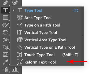
The Reform Text tool appears in Illustrator’s main toolbar (which must be in Advanced mode: View > Toolbars > Advanced) stacked under the native Text tool. As with other stacked tools, click and hold on the top tool icon to display the tools stacked under it.
You can also click on the Reform Text panel to activate the tool. To locate the Reform Text panel from the menu, go to Window > Astute Graphics > Reform Text. Initially all the controls will be greyed out. This is because Reform Text needs one Text Box object and one path to be selected before it can place the text on the path. When these two objects are selected, the Make button will become available. Clicking the Make button will activate the other controls, and the selected text should be placed on the selected path.
The Text Box object is not destroyed by this process, though it will not appear in the rendering of the artwork. The text remains editable until the art is expanded, at which point it turns into regular paths. The path also remains editable using the normal Illustrator tools.
The Reform Text tool has two modes, the basic mode and the variable height mode. Most of the time the basic mode will be used. The modes are toggled with the “show markers” checkbox.
This diagram shows a Text Box in the process of being reshaped along a path using the Reform Text tool in basic mode (with the default interface settings).
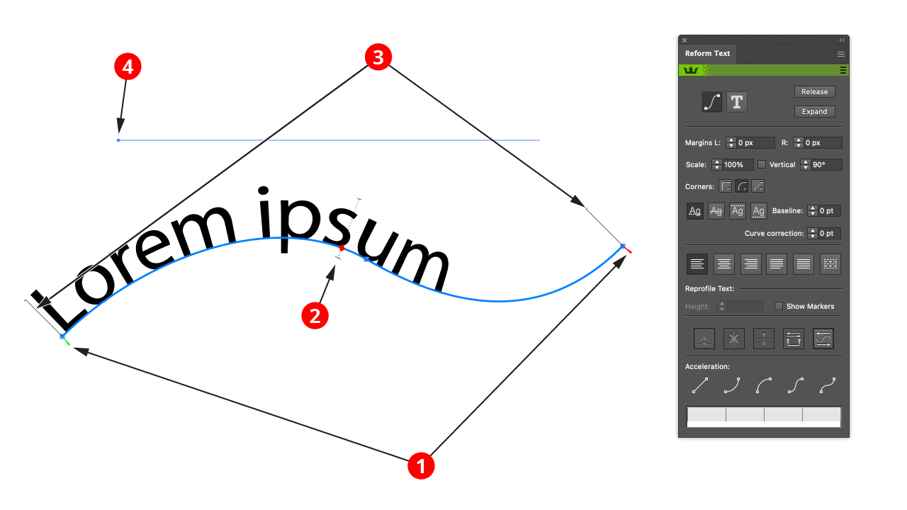
1. Start and end delimiters (green + red triangles)
The delimiters mark the section of the path which Reform Text considers. This is important for left aligning, right aligning, or justifying text.
2. The centerpoint (red diamond)
This represents the center of the path section marked out by the delimiters. By clicking and dragging on it, the text can be moved along the path easily and efficiently.
3. Height Stems (thin black lines)
These show the height of the text, and are a visual cue to help placement.
4. Original Text Box object (thin blue line)
The original Text Box will be shown as a thin blue line by default. Whilst adjusting the delimiters or the centerpoint with the cursor will highlight the original text.
This diagram shows a Text Box in the process of being reshaped along a path using the Reform Text tool in variable height mode (with the default interface settings). To activate variable height mode the Show Markers option in the panel must be enabled.
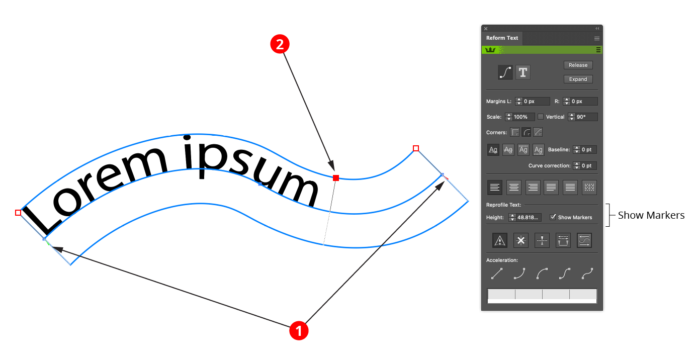
1. Start and end delimiters (green + red triangles) As in the basic mode (see above).
2. Height Markers (red diamonds)
Markers represent points along the path where the height of the text is specified. A marker’s position along the path is indicated by a small black square, joined to it by a thin black line whose length represents the text height at that point.
Markers drawn as circles are “smooth” markers: the reshaped path passes smoothly through them.
Markers drawn as diamonds are “sharp” markers: the reshaped path can make an abrupt angle change there.
You can use any number of markers to reshape a path, but, like anchor points, for the smoothest results you should use the fewest number that still produce the shape you want. They work in a similar fashion to Reform markers, the difference is that whilst every Reform path uses markers, only occasionally is there likely to be a need for variable height text.
Text can be edited either from the Reform Text panel or by using the tool. Virtually all operations are available from both, but sometimes it is easier to work interactively with the cursor, and sometimes it is easier to enter values into the panel.
The delimiters can be moved by dragging them. To disable snapping to anchor points, hold down Command/Ctrl while dragging. To quickly move the delimiters so that the entire path is affected by the Reform Text tool, double-click either one of them. This will move them to the path’s endpoints. If a delimiter is dragged such that a marker would fall outside of the newly-delimited portion of the path, the marker will be automatically deleted. If a marker is located exactly on a delimiter, then moving the delimiter will also move the marker.
Markers can be moved by dragging them within the delimited reshape extent. To disable snapping to the path’s underlying anchor points, hold down Command/Ctrl while dragging. Dragging a marker by its circle annotation will allow you to freely change both its position along the path and its offset; to change only its offset, hold down Shift while dragging.
To change only its position, drag the marker’s black line.
To select a single marker, click on its red annotation shape.
Multiple markers may be selected by Shift + clicking them or by dragging a marquee over them in the normal manner.
To delete a marker, double-click its red shape.
To create an additional marker, place the cursor over either the original or virtual reshaped path and click or click-and-drag.
To change a marker from smooth to sharp or vice versa while dragging it, press the X key.
When using the Reform Text tool, Astute Graphics’ AstuteBuddy panel should be kept open to show relevant keypresses.
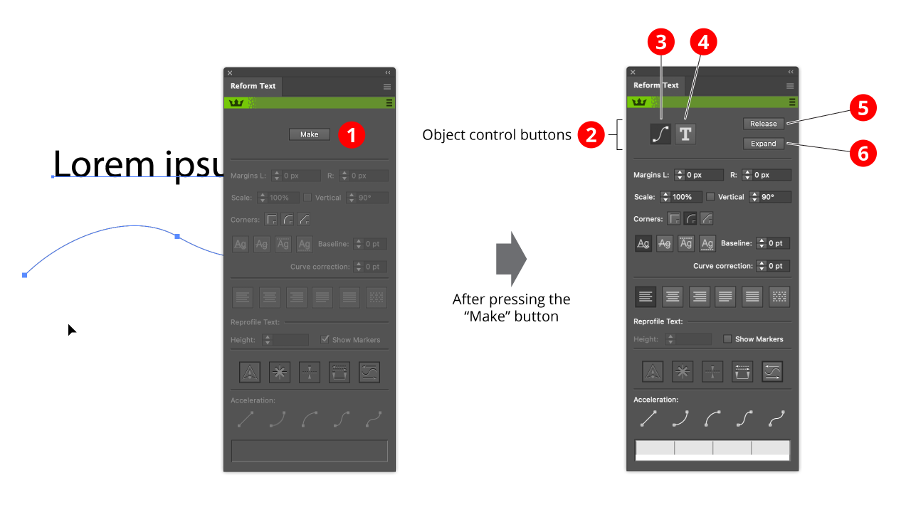
1. Make button
This is available when one Text Box object and one path is selected. It creates a Reform Text object from the two elements. The Text Box object and the Path object are not deleted, but they are moved under the control of the Reform Text object, and will not be rendered.
2. Object control buttons
When a Reform Text object is created and selected, the Make button disappears and the Reform Text object control buttons appear.
3. Edit Path button
This radio button makes the path editable by standard Illustrator path editing tools. Reform is especially recommended as a powerful and intuitive path editor, but you can also use the native anchor point tool.
4. Edit text button
This radio button makes the text editable. The text will appear in a box. Click on the text box to obtain a caret, which can be used in conjunction with the other text entry tools to edit the text. It is not possible to edit the text in place on the path, but edits will be echoed to the text on the path interactively.
5. Release button
This deletes the Reform Text object, releasing the Text Box object and the path back to normal Illustrator control.
6. Expand button
This turns the Reform Text object into regular artwork. The Text Box object and the path will be deleted, and Illustrator no longer understands the artwork as text. plugin. Some of the preference can be changed on the fly when dragging artwork, by pressing various keys (see Rotate At Collision: Tool Operation).
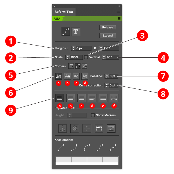
1. Left and Right margins controls
This is an alternative to dragging the delimiters. Enter a value or use the arrow keys to adjust the position.
2. Scale control
Resizes the text to a given percentage of its original size.
3. Vertical checkbox
When checked, the text is vertical rather than rotated in the direction of the path. This option is useful for curves which represent 3D transformations.
4. Vertical angle control
By default 90 degrees is “vertical”.
5. Corner buttons
Defines the behaviour when text goes around a corner. There is no good way of flowing text around a sharp corner other than adding spaces to ensure that glyphs do not break on the corner. However if text is in fact non-text symbols, corner behaviour might be crucial.
6. Baseline radio buttons:
Text can be:
a: placed with its baseline on the path (normally what you want) b: placed so that the path goes through the text midpoint.
c: placed so that the path touches the top of the text.
d: placed so that the path touches the bottom of the text.
7. Baseline offset control
The text baseline can be further refined with the baseline control.
8. Curve correction control
Adjust how the text distorts when going round curves. The value represents the adjustment to the offset from the curve. If text is not distorted nicely around sharp curves, setting this value will change the distortion.
9. Justification radio buttons:
a: align to left delimiter
b: align to the center of the delimiters
c: align to right delimiter
d: justify (reflow text and adjust spacing so that lines fit exactly in delimiters)
e: scale the text until it fits exactly within the delimiters
f: scale the text horizontally but not vertically until it fits exactly within the delimiters
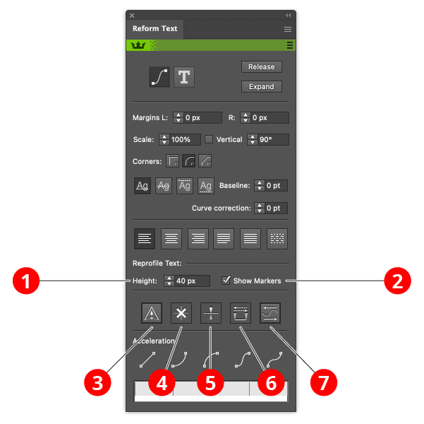
1. Height control
Set the height of a marker by entering a value.
2. Show markers checkbox
When unchecked, the tool is in basic mode. When checked, it is in variable height mode.
3. Sharp marker button
Toggles the selected markers between smooth and sharp (see above for explanation of different types). It also controls the type of any newly-created markers.
4. Delete marker button
Removes all selected markers.
5. Mirror offset button
Changes the direction of the offset of all selected markers. This is the same as changing the sign of the offset value.
6. Swap marker direction button
Changes the position of all markers (selected or not) along the reshape extent. If, for example, a marker is located 1/5 of the way from the start to the end delimiter, swapping the direction will change it to be 1/5 of the way from the end to the start delimiter. Offset values are not changed.
7. Reverse flow direction button
Reverses the direction of the text. Used in conjunction with the Mirror offset button it turns text upside down instead of reflecting it.
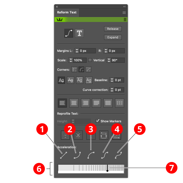
Acceleration refers to distortion of the text in the horizontal direction. This is useful for 3 dimensional or other special effects. The buttons are control buttons and it is possible to further edit the acceleration in the Acceleration widget to have fine-grained custom control.
1. Linear acceleration button
The default. No acceleration or uniform acceleration.
2. Ease in acceleration
Text starts very stretched, then becomes very compressed.
3. Ease out acceleration
Text starts very stretched, then becomes very stretched.
4. Shallow sigmoid acceleration
Text starts very compressed, becomes very stretched, then ends very compressed. This one is set up to represent text printed on cylindrical object such as a can or a bottle.
5. Steep sigmoid acceleration [A misnomer]
Text is uniform, but here are two handles which you can use in the acceleration widget control to define your own sigmoid acceleration profile easily.
6. The acceleration widget
This displays the acceleration graphically, and allows for fine control or custom accelerations.
7. Acceleration widget control handles
With a linear acceleration you get no handles (no editing possible), with ease in or ease out one handle, and with the sigmoid controls, two handles. Grab and pull the handles, and the acceleration adjusts
to reflect the new handle position. Note that sometimes the handles will appear to get stuck. This is to prevent the entering of extreme accelerations which would produce undesirable results.
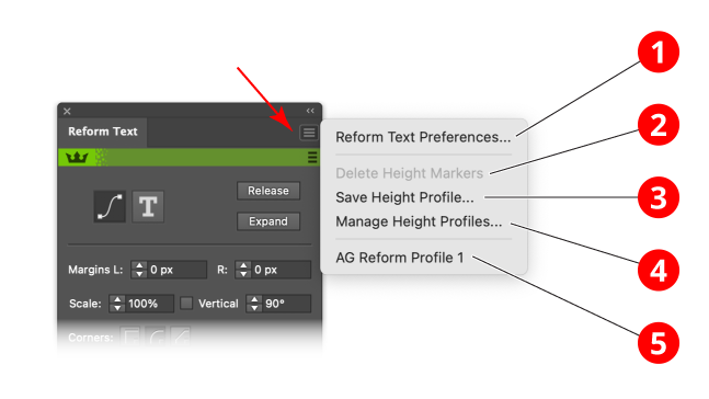
The flyout menu gives access to the profiles library, which is shared with the other tools in the Reform suite, Reform and Reprofile. In Reform Text, the markers represent the height of the text, and so are referred to as “height markers”.
1. Reform Text Preferences
Goes to the Reform Text Preferences panel..
2. Delete Height Markers
Convenience function delete all current height markers.
3. Save Height Profile
Adds the current height profile to the profile library.
4. Manage Height Profiles
Opens a dialog to allow deleting and renaming of stored profiles in the profile library.
5. Stored height profiles
List of available stored height profiles. Shared with Reform and Reprofile.
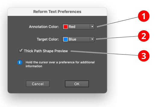
1. Annotation color
The color of the width markers in variable height mode.
2. Target color
The color of the edit path, and the guide paths in variable height mode.
3. Thick path shape preview
When set, the edit path and the guid paths are draw with thick lines.
Reform Text is implemented as an Adobe Illustrator plugin group. This means that it takes control of the so-called edit art, in this case the Text Box object and the Path object. However the edit art is still editable using all of Illustrator’s functionality. However due to some internal problems to Illustrator we have had to provide special logic to allow interactive editing of text. Hence it is necessary to have a mode for editing the text and a mode for editing the curve.
By pressing the Release button, the Reform Text object will be deleted, and the edit art will be placed back on the artboard. If there are problems editing the edit art, due to weaknesses in the Illustrator system, then releasing the edit art then applying Reform Text again with the Make button is a workaround.
The text on the path is the result art. The resulting art is the art that is passed to Illustrator for rendering. You can apply styles to it in the normal manner. However it cannot be manipulated. To do that, it is necessary to expand it. This will delete the Reform Text object, the Text Frame object, and the path. You can expand either using Adobe’s native expand menu command Object > Expand Appearance or the Expand button shown in the panel. Whilst these should achieve the same result, they use different logic internally. The Astute Graphics button is provided partly for convenience, partly so that there is a fallback if one expand command fails.
Operational
Sculpt or reshape any unlocked path
Refine all changes to a path before applying or cancelling
Apply changes instantly, maintaining all other original path attributes (color, transparency, etc.)
Resultant paths 100% standard, with no evidence Reform was used
Works directly with all vector shapes, compound paths, clipping masks, text base-lines, etc.
Sculpt mode, ideal for regions to whole paths (open or closed)
Looped mode, ideal for closed smooth paths (effectively, variable offset)
Constant offset mode, ideal for offsetting a region of a path
Annotation preview showing potential changes to the path
Interactive controls
Define one or more offset values at any position along a defined path region, or the whole path
Click-and-drag offset markers, optionally maintaining position along path or offset distance
Switch between Sculpt and Looped modes
Marquee-select multiple offset markers
Click-and-drag multiple offset marker or numerically merge to constant offset value
Panel controls
Numerical control for offset marker(s)
Variable transition smoothing to elegantly merge sculpted, reshaped path to original
Corner types: Mitered, Rounded and Beveled
Define any marker as smooth or corner
Mirror selected marker(s) across path
Swap direction of all offset marker
Smart Join option for intelligent merging of path shape at ends of the reshape region
Advanced clipping option to disable automatic, intelligent clipping of reshaped path
Profiles
Save and recall user-defined sculpt and looped Profiles
Apply saved Reform Profiles to any region of, or entire other paths
Manage Profiles with rename and delete options
Profiles stored across all Illustrator sessions
Preferences
Annotation colors
Think/thin annotation lines for maximum visibility or precision
Integrated Smart Point Removal (unique Astute Graphics technology to optimise the number of resultant points)
Move Points to Tangencies to better place resultant points like a pro
Edit Selected Path Only to assist editing complex, layered artwork
Work faster with keypresses
Keypresses available throughout editing process to speed up workflows
Works with Astute Buddy plugin to provide context-sensitive key shortcut information, when you need it
Operational
Apply a repeating vector profile any unlocked path
Use any of the sample profiles or create any unique vector profile to suit
Subscribers gain access to additional professional, themed Profile packs
Adjust variable heights, direction, repeat frequency, and more, before applying or cancelling
Apply changes instantly, maintaining all other original path attributes (color, transparency, etc.)
Resultant paths 100% standard, with no evidence Reprofile was used
Works directly with all vector shapes, compound paths, clipping masks, outlined text, etc.
Optionally apply the chosen profile to whole paths, open or closed, using the Looped mode
Quickly apply to a path section between corner points using the Constant Offset mode
Annotation preview showing potential changes to the path
Interactive controls
Define one or more profile height values at any position along a defined path region, or the whole path
Click-and-drag offset markers, optionally maintaining position along path or offset distance
Switch between standard (including Constant Offset) and Looped modes
Marquee-select multiple offset markers
Click-and-drag multiple offset marker or numerically merge to constant offset value
Panel controls
Numerical control for offset marker(s) height
Define the repeat distance (profile repeat frequency)
Corner types: Mitered, Rounded, Beveled and Mirrored
Enable/disable Break mode, forcing profiles repeats between sharp corners
Variable transition smoothing to elegantly merge profile form to original path
Optionally scale profile frequency based on height (to maintain a proportional appearance)
Define any marker as smooth or corner
Delete selected marker(s)
Mirror selected marker(s) across path
Swap direction of all offset marker
Flip profile direction
Fidelity (quality) of result, offering advanced control over maintaining straight profile segments
Profile management (panel and manager windows)
Create custom profile based on an open key path, plus any additional paths (open or closed)
Edit any existing profile property
Custom profile categories
Optionally suppress key path (not rendered - only used for placement purposes)
Place instance of profile onto artboard (allowing for easy editing)
Replace existing profile with selected artwork vectors
Profile properties (default values): name, key path selection, suppress key path, category, height, repeat distance, corner type, break
Profile manager window: preview, rename, category control, import and export profiles (interchange between users), delete profile
Width profiles (profile height markers)
Save and recall user-defined standard (including Constant Offset) and Looped width profiles
Apply saved Reform and Reprofile width profiles to any region of, or entire other paths
Manage Profiles with rename and delete options
Profiles stored across all Illustrator sessions
Preferences
Annotation colors
Think/thin annotation lines for maximum visibility or precision
Integrated Smart Point Removal (unique Astute Graphics technology to optimise the number of resultant points)
Edit Selected Path Only to assist editing complex, layered artwork
Operational
Elegantly distort any editable text, including point text and paragraph text, along a path
Text and baseline path both remain fully editable
Each character/glyph fully follows bends and corners in the path
Intuitive and powerful text placement including center placement, alignment, direction and padding
Unlimited baseline offset controls
Optional variable height controls can be applied at any stage along the distortion, including twisting across the baseline path
Acceleration control allow pseudo 3D or creative effects to be applied dynamically
Clean and high quality editable paths if the result is expanded
Interactive controls
Define one or more text height values at any position along a defined region, or the whole path
Click-and-drag left and right margins, center points and height markers
Marquee-select multiple height markers
Click-and-drag multiple height markers or numerically merge to constant offset value
Panel controls
Modes to edit text along a path or original text
Release or Expand the result artwork
Numeric controls for:
Left and right margins
Text scale
Optional common text slant angle
Sharp baseline corner method (mitred, rounded or bevel)
Baseline offset controls including numerical fine-tuning
Curve correction to adjust visual acceleration of text around sharper baseline curves
Text alignment (left, center, right, justify)
Text height marker numerical control
Height marker controls including sharp, delete, mirror, flip and swap
Acceleration strategies including linear, ease in, ease out and ease in/out, with proportional controls for each
Profile management (panel fly-out menu and manager windows)
Save, manage, rename and delete custom height profiles
Replace existing height profile with pre-saved custom profile
Preferences
Annotation colors
Think/thin annotation lines for maximum visibility or precision