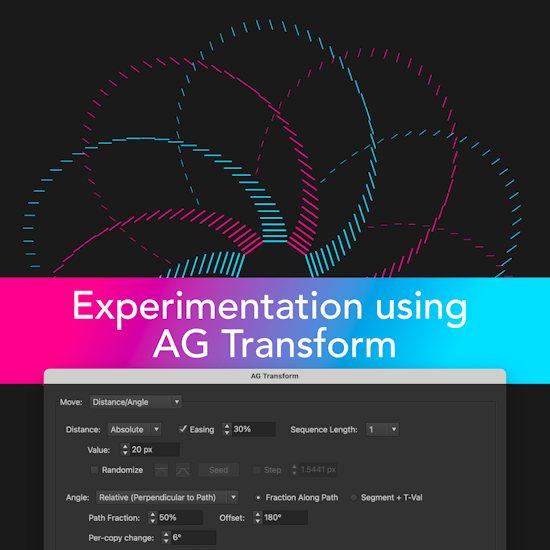
Experimentation using AG Transform
13 minute readAG Transform, Astute Graphics’ newest addition to the AG Utilities live effects suite, lends itself well to experimentation. Because it has numerous, interacting parameters and options, serendipitous discoveries of interesting appearances can arise from simply changing those parameters to see what happens. Since it’s a live effect, no permanent changes are ever made to the artwork, which can always be returned to its original state. Note: screenshots for the AG Transform parameters dialog are not shown below due to its large size. However, you can follow along with the “experiments” by opening the accompanying files.
Part 1
Please use this link to download the Illustrator file and follow along with this experiment: https://bit.ly/AGTransformBlog
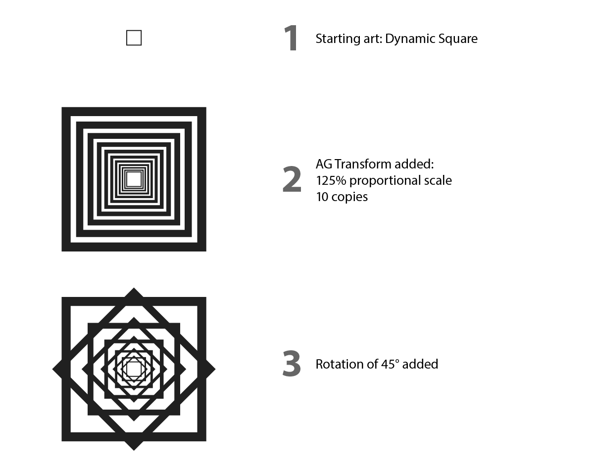
We’ll start with a very simple piece of art — a 15 pt square with 1 pt stroke, and no fill.
Let’s apply an AG Transform effect to the square. In the parameters dialog that comes up, under the “Scale” section, we change the scaling to 125% (proportional). The Scale Point will be left at its default of “Relative to Bounds” (center) and “Top-Level Art”. At the bottom, we change the number of copies to 11.
Now let’s try adding a rotation component — say, 45°. The Center of Rotation is located, by default, in the same place as the Scale Point (the center of the art), so the squares remain concentric.
Since 360 is divided by 45 evenly, the design stays rather simple.
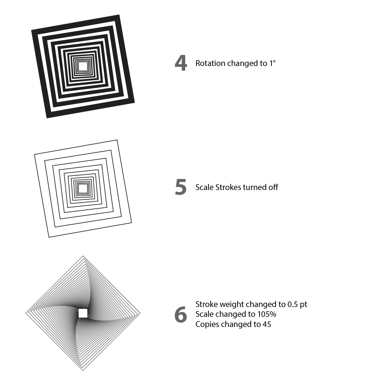
After changing the rotation to a much smaller value, like 1°, the look is more interesting and could possibly serve as a background design element using a lighter color.
Turning off the Scale Strokes setting seems to make things look somewhat plain.
But with thinner, consistent strokes, we can now make the copies of the squares closer together. We’ll reduce the stroke weight to 0.5 pt, change the Scale value to 105%, and increase the number of copies to 45.
Of course, while fascinating, this design has been created many times before. Indeed, everything we have done so far could also be done with the native Transform effect.
Let’s use some of AG Transform’s unique features to try and achieve a more original design.
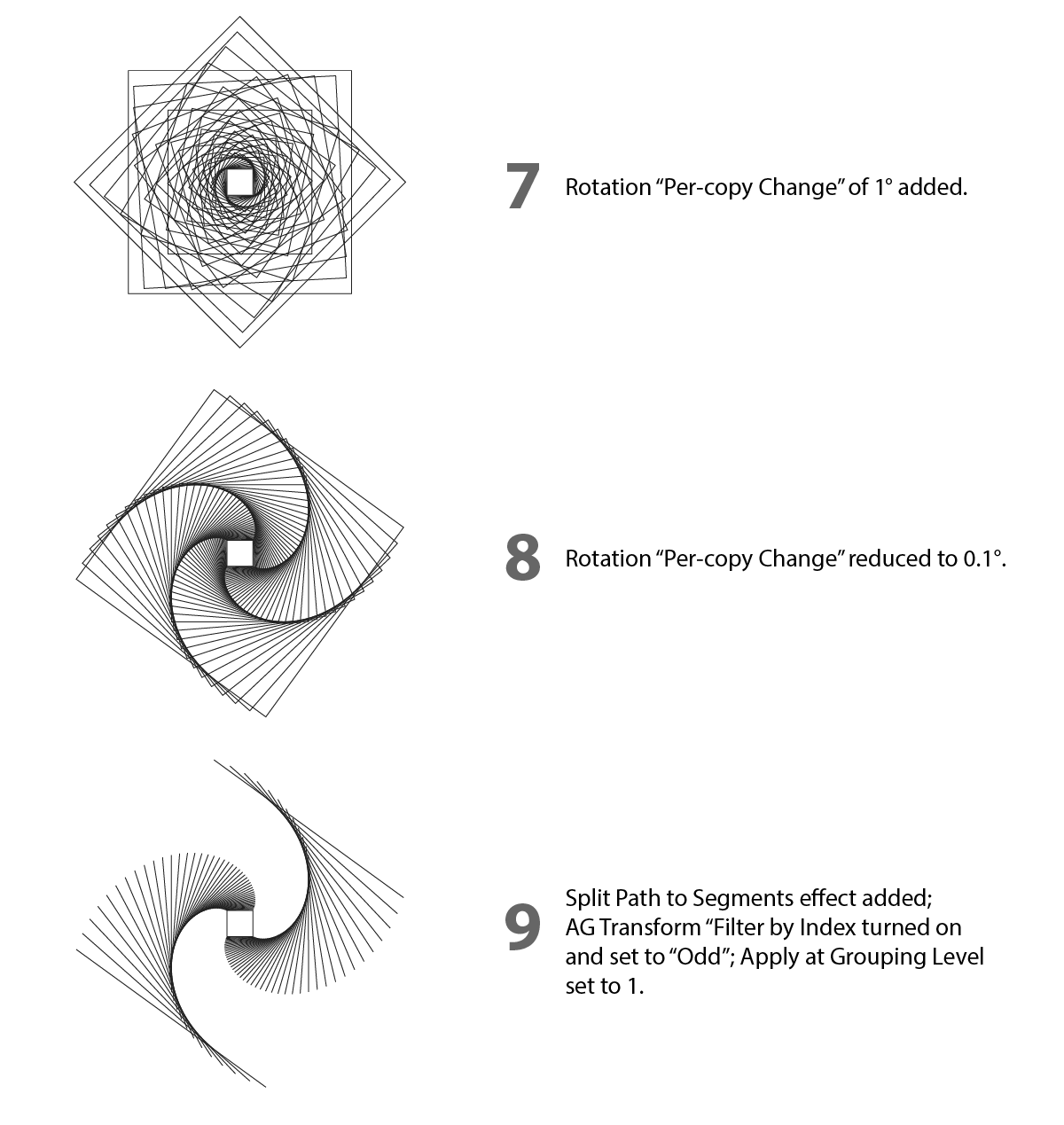
First, note that AG Transform implements a “Per-copy Change” value for the rotation. In other words, each successive copy can be rotated by a different amount. If we try 1° for this parameter, we get a vaguely-spirographic (but somewhat cluttered) look.
A smaller value — here, 0.1° — looks more pleasing. However, the overall appearance is still similar to what we had earlier. What if we transformed only two of the sides of the square?
Since AG Transform allows “filtering” the input art according to its index (i.e., the simple sequential order in which it is seen by the effect), this is easy — if we can first break the square into its four sides.
We could do this manually, but the goal is always to do things in a reversible way when possible. So here we can simply place another AG Utilities effect, “Split Path to Segments,” above the AG Transform in the Appearance panel. Then we turn on “Filter by Index” in AG Transform, and set it to “Odd”. We also need to change the AG Transform “Apply at Grouping Level” setting to 1, so that the effect looks at each side individually within the passed group.
The overlapping lines along the outside are a bit unsatisfying. What if we scaled the lines from one end instead of the original art’s center point?
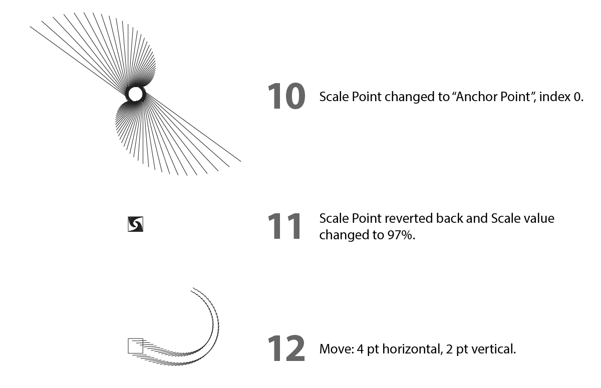
We can easily accomplish this by changing the AG Transform “Center of Rotation” parameter to “Anchor Point,” with the index set to 0.
While interesting, this obscures the original shape in the center too much. Let’s change the Center of Rotation back to “Relative to Bounds” and make the lines smaller rather than bigger, by changing the scale to 97%.
Oops, this is not what we wanted. We clearly need to move the lines, in addition to scaling and rotating them.
We’ll start with the default horizontal/vertical offset that you would find in the native Transform effect (here, 4 pt horizontal and 2 pt vertical). The results shows its limitations: both sides move the same way. It would be nicer if each side moved differently (and, preferably, symmetrically). Fortunately, AG Transform has an alternate Move mode (Distance/Angle), so let’s use it.
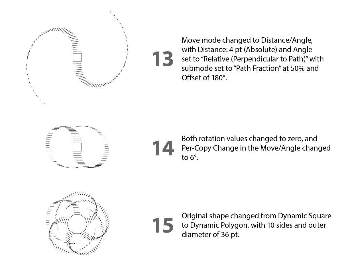
By setting the Move Angle to “Relative (Perpendicular to Path)”, we can move each object in a manner relative to the path’s angle. We can specify the spot at which to calculate the perpendicular angle, but as these paths are just straight lines, the midpoint is fine. We need to add an overall offset of 180° to get them to move away from the center due to the direction of the paths (we could, alternatively, reverse the path direction of the original square).
Note that since the lines are still being rotated, they do not remain parallel to each other. If we remove that rotation, the lines will simply extend out without curving, which is too simple.
However, there is another way to create curved motion.
AG Transform’s Move (Angle) section also has a Per-copy change value that can be utilized. By setting this value to 6°, the copies of the line remain parallel (they are no longer being rotated) but still curve around, because each copy is being moved in a different direction relative to its perpendicular.
And now the power of using live effects exerts itself. By simply using the Dynamic Shapes panel to change the original path shape from a square to a 10-sided polygon, we get a great new look — and an idea comes to mind. What if we made the polygon (and the extending lines) using two different colors?
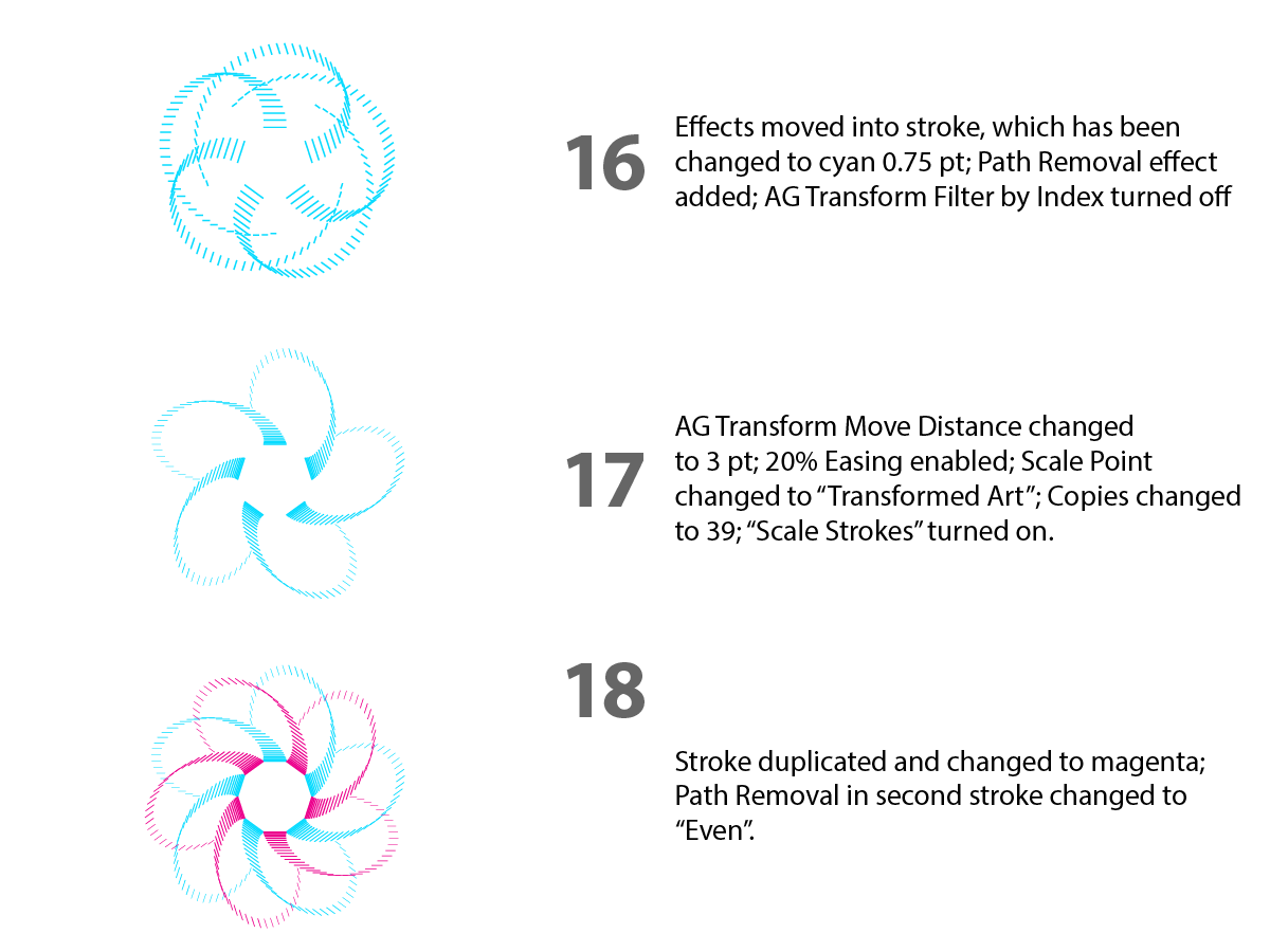
We’ll change stroke color and weight, and, in preparation for creating the shape with two differently-colored strokes, we’ll move all the effects into the stroke. Using AG Transform’s Filter by Index won’t work so well anymore, because the non-transformed paths would still be visible (unless we turn on “Remove Original,” but we’d like to keep the central polygon).
So our alternative is to put a Path Removal effect above the AG Transform (inside the stroke), and use it to remove half the sides.
The design would probably look better if each set of lines that are of one color did not overlap each other — and a few tweaks of the AG Transform parameters lets us do this. Here we’ve changed the Move value to 3 pt, enabled Easing (at 20%), changed the location of the Scale Point from “Top-Level Art” to “Transformed Art”, turned “Scale Strokes” back on, and reduced the number of copies to 39.
And now all we need to do is duplicate the stroke by selecting it in the Appearance panel and clicking the “+” button. All its effects are duplicated too. We change the second stroke’s color to magenta and its Path Removal “Index” parameter to “Even”.
Remember that everything is still live — for example, changing the number of sides of the Dynamic Polygon could create many more interesting designs.
Part 2
Please use this link to download the Illustrator file and follow along with this experiment: https://bit.ly/AGTransformBlog
For another example of how AG Transform is tailored to experimentation, consider a simple path with a Make Shape live effect (used to create rectangles along the path; unlike dashes, each rectangle is always straight, even if the path is curved):

We’ll add an AG Transform effect with two copies and a sequence of two Move operations (using Distance/Angle mode). The first copy will be moved upwards (perpendicularly to the rectangle’s top edge) by 6 pt; the second will be moved downwards by 12 pt. This has the effect of “tripling” each rectangle while keeping them centered on the path:

Now we’ll add a second instance of AG Transform. This will be set to Grouping Level 2, which will let it affect each internal group of three rectangles created by the first AG Transform effect. By using a Rotate value of 90° and a Filter by Index set to Odd, every other group will be rotated, giving this nice effect:

While appearances such as these can certainly be created using brushes, that method is not particularly conducive to experimental tweaking to try out different configurations, including those that we may not have thought of doing manually.
However, since we’re using live effects, we can start altering various parameters to see if anything interesting is produced. For example, what if we changed the Grouping Level to 3, such that each rectangle is affected individually?

This is perhaps a bit unexpected, but can be made sense of if we remember that the rectangles are being created in the order middle–top–bottom for each set of three that are stepped along the path.
The spacing now looks rather loose, so let’s go back to the Make Shape effect and tighten it up:

Now let’s experiment with the Filter by Index parameter on the second AG Transform. Instead of setting it to “Odd,” let’s change it to “Pattern,” with values Initial Skip at 0, Match at 2, and Skip at 1, which we can write more concisely as (0/2/1):

Let’s increase the Match value to 3 (0/3/1):

And now (0/4/1):

And finally (0/5/1):

Note that when the Match plus Skip value equals a multiple of three, we get symmetry. For another example, let’s change the “Pattern” values to (0/3/3):

For one final twist, we’ll change the Rotate angle from 90° to 30°:

Part 3
Please use this link to download the Illustrator file and follow along with this experiment: https://bit.ly/AGTransformBlog
For our final “experiment,” we’ll examine how adjusting the AG Transform Rotate amount and the Center of Rotation position can generate new ideas and designs.
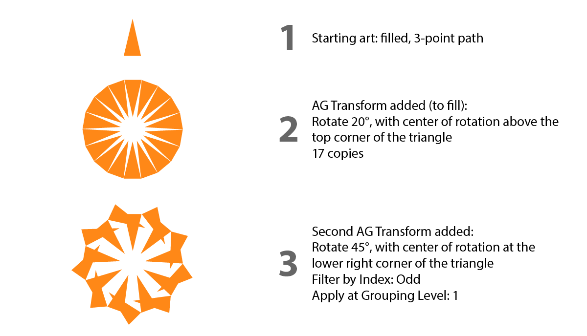
The starting art is a filled triangular path.
We apply an AG Transform effect to the triangle, putting it inside the fill in case we later want to add additional fills. In the parameters dialog that comes up, under the “Rotate” section, we specify 20°. We want the triangle to be rotate around a point above its top corner. Noting the indices of the path’s anchor points (in this case the bottom left point is 0, and the path is clockwise), we change the Center of Rotation method to “Along Line” with the starting point equal to “2 / 0.5” (midway along the bottom edge) and the ending point to “1 / 0” (the top point) and the fraction to 134%. At the bottom, we change the number of copies to 17.
To create a variety of designs, it makes sense to transform only some of the art. So we add a second AG Transform effect below the first (with “Filter by Index” set to Odd and “Apply at Grouping Level” set to 1). This will make it affect every other triangle, and we’ll start by rotating them 45°. We’ll start with the center of rotation at the triangle’s lower right corner. To do this we could specify it using “Anchor Point” set to 2, but to retain the ability to move it freely later, let’s use “Along Line” again, with the parameters 2 / 0 to 1 / 0 at 0%.
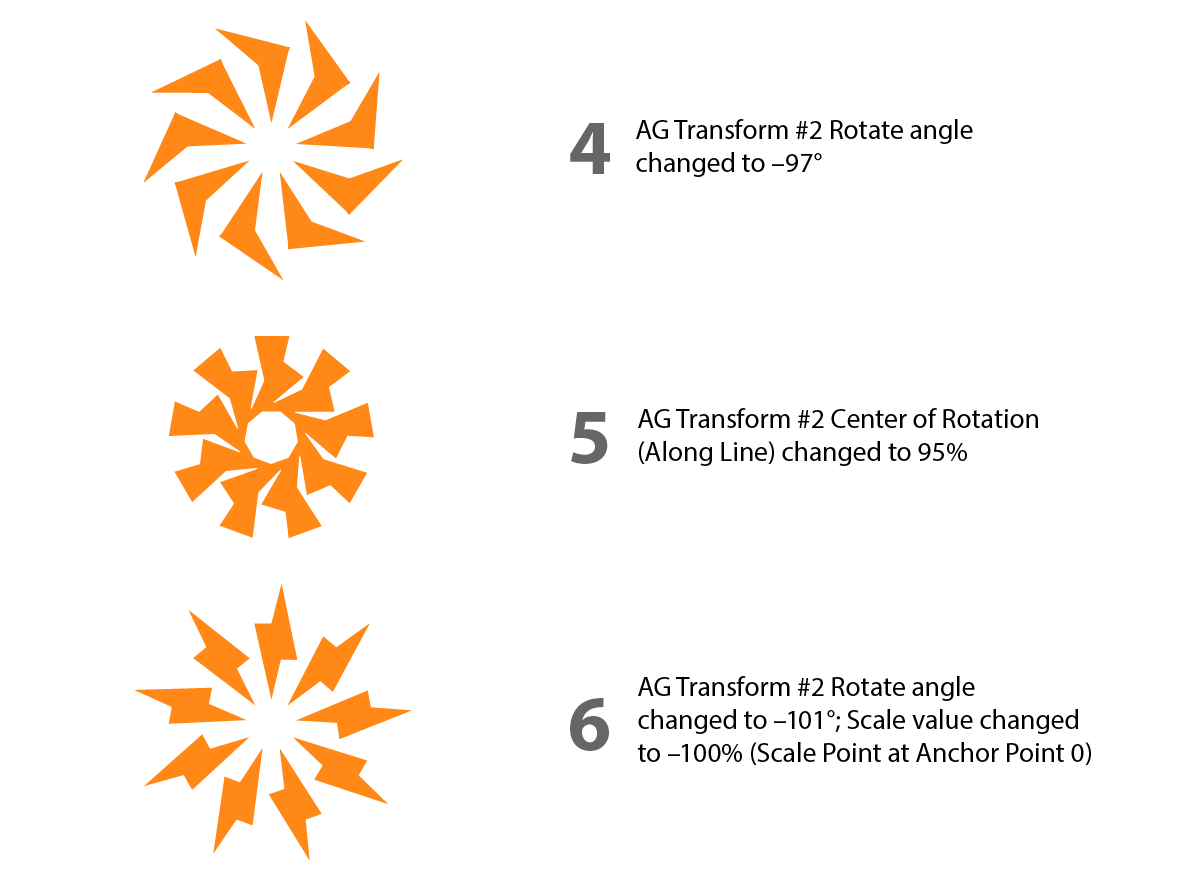
Let’s try a different Rotate angle. –97° creates a nice effect.
And now we can experiment with moving the Center of Rotation. Here’s it’s been changed to 95% along line.
To get a different look, let’s flip the odd-indexed triangles around. We can do this independently from rotation by changing the scale from 100% to –100% (with the Scale Point at Anchor Point 0). We’ll also tweak the Rotate angle to 101° to get this “electrified” look.
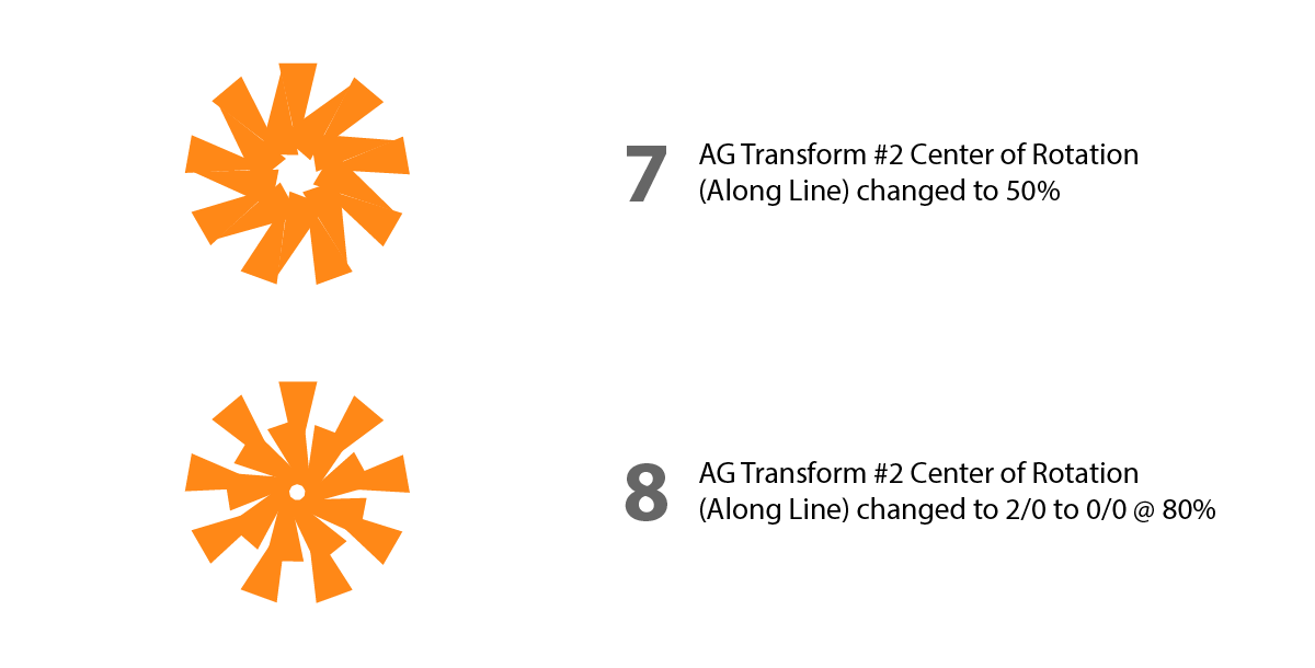
Playing around some more, a Center of Rotation Along Line value of 50% gives this interesting figure.
Finally, we’ll try one more experiment. We’ll put the Center of Rotation along a different edge, by changing the starting point to 2 / 0, the ending point to 0 / 0, and the fraction to 80%.
These examples, of course, are only the tip of the iceberg. Especially when combined with other effects in an effect stack, AG Transform can provide endless opportunities to find novel and interesting appearances, for those willing to experiment with its parameters.
Try Astute Graphics for FREE
If you haven’t tried the hundreds of features available from Astute Graphics for Adobe Illustrator, you can use it free for 7 days. No payment details are required.